DIESEL LOCOMOTIVE

January 2003

DIESEL LOCOMOTIVE MODELPLAN

INTRODUCTION

Bogies and Chassis

Bumpers and Undercarriage

Cabin and Body

Roof and Fans

Optional Components

Mounting the components and The Track

PARTS LIST


Seats


A corner bracket (p#133a) is bolted ¾” the way up a 2” threaded rod (Fig 11a). Two nuts are lock nutted at the bottom and it pivots through a crank bolted to the cabin floor. Two nuts lock nutted underneath allow it to rotate. The threaded rod bolts into a threaded rod adapter. Place a spring over the exposed rod of the adaptor and bolt a small bush wheel onto the end. A 1” flat girder and triangular plate (Fig 11b), part number 76, make up the rest of the seat with a ½” bracket bolting it to the 1” 6 hole bush wheel (p#518).

Toilet

Bolt two 2” angle brackets into a U girder. Bolt 2” flat girders to the outside. Bolt another 2” angle girders on the other side and another 2” angle girder across the top. Below, bolt a triangular plate (p#77). A ½” bolt passes through the bottom hole of the triangular plate and lock nuts into the boss of the ¾” wheel flange. A 11/8” bolt bolts the toilet to the chassis spaced by two collars.

Body


Starting from the rear, bolt a 4½” strip, 2½” x 4½” plate and an obtuse angle bracket to the end round hole of a 24½” angle girder (Fig 12a). Next to the 2½” x 4½” plate (Fig 12b), bolt on another 2½” x 4½” plate (Fig 12c) overlapped by two holes. Bolt six plates together like this up to the 20th hole.

Bolt a vertical 4½” strip to the 20th hole. Skip eight holes and bolt a 4½” strip and another 2½” x 4½” plate. Bolt four together up to the 42nd hole. Bolt a vertical 4½” strip to the 42nd hole. Skip three holes and bolt a 2½” x 4½” plate (Fig 14a) sideways with a 2½” strip over the plate’s oval holes. Butt join a 3” angle girder to the 24½” girder using a 2½” strip inside the plate.

Across the top of the side-plates, butt join two 12½” strips (Fig 12d) with a 2½” strip. The top of the roof is curved in using butt joined 12½” strips (Fig 12e). They are placed using regularly spaced obtuse angle brackets and fishplates.


The rear is made up from three 2½” x 3½” plates overlapping each other to form a 5” x 3½” plate. 3½” strips and 4½” strips form the ends. Next the two sides are joined together with the rear end. On each side of the rear plate, two 4½” strips (Fig 13a) are bolted together with obtuse angle brackets and fishplates top and bottom. The 3½” strip (Fig 13b) across the top of the composite 5” x 3½” plate has obtuse angle brackets and fishplates as fillers on its ends.

Using obtuse angle brackets, bolt a composite 4” strip (Fig 13c) from 2 x 2½” strips with obtuse angle brackets on the ends. Using 4½” threaded rods and threaded bosses (Fig 13d) as anchors, form a ladder with four ½” narrow strips. At the rear, on each side, form a handrail support using collars (Fig 13e) and 3½” threaded rods locknutted on.


 Join 
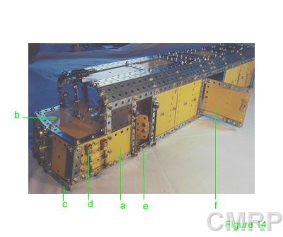
the front with a 2½” x 5½” plate (Fig 14b) forming the bonnet. It must line up with the front edge of the sideways 2½” x 4½” plates. Bolt a curved 5½” strip across the front of the top plate. The front is made up from a 2½” x 5½” plate (curved slightly).Bolt a 5½” strip (Fig 14c) across the bottom, spaced one hole down with fishplates. Use 2½” strips on the edges of the bonnet plate, side plates and front plate to neaten up.Bolt ¾” flanged wheels to the front as lights. I placed LED lights in mine, wired up to the battery box used to power the motor for the fans.

One hole from the front, using threaded bosses (Fig 14d) at the top end, 2” threaded rods create a ladder with two 2½” narrow strips. The side windows are 1½” x 2½” clear plates, held in a frame made of 2½” narrow strips bolted to the 12½” strip and 2½” x 4½” plate. The driver doors are two 1½” x 1½” plates bolted together to form a 2” x 1½” plate. Two hinges hold the doors on.

A step is made from angle brackets and a 1½” strip (Fig 14e). Handrail supports on either side of the door are made up with collars and 3½” threaded rods locknutted to the rods. 


The front window is made of two 1½” x 5½” clear plates joined to each other to form a 2½” x 5½” plate (or you could use a 2½” x 5½” clear plate).

A center 2½” narrow strip and angle bracket secures the middle, with angle brackets holding on the ends.  The top is curved into the body a bit.

The access doors are made up from two 2½” x 3½” plates together to form a 4” plate (Fig 14f). 2½” strips across the top and bottom neaten up the holes. A latch is made up from a cam, locknutted to a 1” narrow strip on the other side. The door is held on with two hinges.


The driver cab partition is made up with two 2½” x 5½” plates (Fig 15a) bolted on with angle brackets.  4½” strips on the sides neaten up the holes.


The front of the cab has a divider under the bonnet.  It is a 3½” x 2½” (Fig 15b) plate with 2½” strips to neaten the holes.  Use angle brackets to attach it to the edge of the 2½” x 5½” plate (bonnet).  The 2” gap allows finger access to the battery box to switch the fans on and off.


Bumpers and Undercarriage    HOME    Roof and Fans