RADIO
CONTROL
July 2007
101
RADIO CONTROL IN MECCANO
With
the prevalence and affordability of modern radio control, almost all Meccano
models I build nowadays are radio controlled. There seems to be a few Meccano
men around who have tried it, fiddled about, blew up components and experienced
extreme frustration trying to make it work. I have written this basic 101
article on connecting up and running a RC Meccano model with the minimum amount
of fuss or technicality.
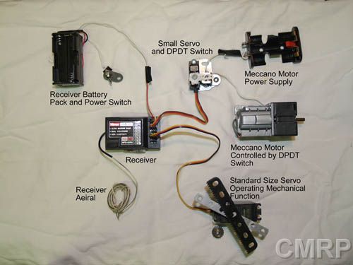
In
example 1, I will demonstrate how to
wire up a model car for a basic two servo control. One servo physically steering
and another turning a switch to reverse and forward for an electric drive motor
(no speed control).
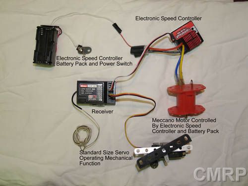
In
example 2, I will demonstrate how to
wire up a model car for a more advanced two servo control. One Servo physically
steering and a forward and reverse electronic speed control “Servo” to
control an electric drive motor with speed control.
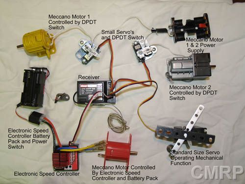
In
example 3, I will demonstrate how to
wire up a more complex model using all the available channels on the Receiver.
In this example, the servos control DPDT (Double Pole, Double Throw) or basic
On/Off switches to control individual motors, using a common or individual power
source. An Electronic speed controller controls one of the motors as well as
powers the receiver and servos.
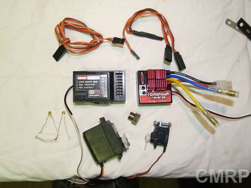
The
Components
Transmitter.
Used
to control the model. They come in a basic two channel control up to an eight
channel control.
Commonly,
all transmitters above four channels will have two paddles controlling four
servos incrementally. The other channels above channel four will commonly
control the rest of the servos on an on/off or centre off, forward / reverse
basis.
Older
basic transmitters will only allow a fixed travel on the servos that cannot be
adjusted. I.e. fixed travel arc of -90^ to 90^ on servo arm.
More
modern Transmitter will allow you to adjust the travel arc of the servo arc
using a LED display on the transmitter. Setting the travel arc on servos is
important as there is a minimal travel arc required to turn a switch on or off
or a defined mechanical movement travel distance needed. It is important to not
force the arm of the servo as it will damage the servo motor / shear servo
gears. Servos can also be set into reverse throw as well which is handy when
setting up and establishing direction of throw needed.
Receiver.
The
make and manufacture of your receiver needs to matched to be compatible to your
transmitter. The correct frequency crystal will need to be matched to the
transmitter and receiver, although newer digital setups no longer require a
crystal to a set frequency but can be programmed dynamically.
Transmitters
will have the same amount of channels as the transmitter, with an extra power
connector.
The
servos are plugged into the receiver’s connector to match the channel required
on the transmitter. Your owner’s manual will help you match your receivers
channel to the required channel on the transmitter or it can be done through
trial and error. Make sure to switch off before plugging in or out anything or
you will risk blowing components!
Power
requirements for the receiver.
The
receiver will need to be powered by a typical 6 Volts in order to power the
servos and receiver itself. There will be a battery connector on the receiver
for this purpose. Consult your owner’s manual if not sure of the power
requirements for your receiver. I always use rechargeable batteries for this
purpose and would not recommend using DC power for this, I have heard of
receivers blowing in this manner. (Time for a Mythbusters special to
prove/disprove this)?
If
using an Electronic speed controller,
the battery connector for the receiver must not be used. The electronic speed
controller will have its own power connector and will provide power to the
receiver through this. Plug the electronic speed controller into the required
servo channel on your receiver and you will see it will power up the receiver
and other servos. Don’t ask me how this works, but it just the way it is!
Typical voltage input to the Speed controller is 4.8V to 8.4V.
Servos
Servos
must be matched to the manufacture of your receiver and your local hobby shop
will be able to advise you.
Servos
can be obtained in a number of sizes from small, medium (Standard) to large.
I
use the small servos to control DPDT and on/off switches. The medium sized
(Standard) servos are used for light duty mechanical operations and the larger
ones can be used to where the medium size servos fall short. The standard servos
can be used to control DPDT and on/off switches where space permits but the
smaller sized servos take up very little space.
Powering
Meccano motors.
The
servo motors are powered by the power supply connected to the receiver or the
power supply from the electronic speed controller.
Meccano
motors controlled by a DPDT or on/off switches need to be
powered by their own battery pack or DC power.
In
the case of a Meccano motor controlled by an electronic speed controller, it
will be powered by the batteries plugged into the electronic speed controller.
These batteries also power the receiver and servos. Any other Meccano motors
controlled by a DPDT or on/off switch need to have their own power supply.
An
important
note is that most electronic speed controllers will
be damaged if they are used to power a motor with no suppression. This is often
why Meccano modelers will have a model running fine for a while and will then
stop working for no reason. I have never had a failure by merely following this
basic rule.
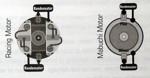
A
104 Micro Farad capacitor (Kondensator) readily available at hobby shops for
this specific purpose needs to be connected to the motor in the following
manner.
-
Solder one of the ends of the capacitor to the case of the motor and the other
end to the Positive terminal of the motor.
- Solder one of the ends of the
second capacitor to the case of the motor and the other end to the Negative
terminal of the motor.
Hooking
it all up
Example
1
Example
2
Example
3
Operation
From
experience it is best to setup each servo’s throw arc and direction while you
are busy building the model.
-
Power on Transmitter first! By turning on the receiver first you risk damaging
the servos as they will have no reference points or control at startup and they
could exceed their travel arc. Electronic speed controllers could also power up
motors with no control.
-
Power on Receiver
-
Move the required controller on the transmitter very slightly to confirm it is
controlling the correct servo.
-
Enter the configuration mode for your transmitter and program the travel arc and
direction for the servo.
-
Once programmed, save the configuration and continue building or test/configure
others if ready.
-
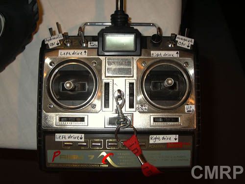
Label the Functions on the transmitter with small pieces of masking tape labels
as this makes it easier to control the model once built. Label all the servos,
battery packs and power switches in the model. When troubleshooting or testing
it makes life much, much easier!
Accessories:
In
larger models, servo control extension cables can be used.
A ‘Y’ splitter can also be used to control two servos from one receiver
channel. Useful where more mechanical power is required for a mechanical
operation.
Reference
table
|
Receiver
|
Futaba
|
JR
/ Graupner
|
Sanwa
/ Airtronics / Hitech / Acoms
|
|
Signal
Wire
|
White
|
Orange
|
Yellow
/ Blue
|
|
Positive
Wire
|
Red
|
Red
|
Red
|
|
Nagative
Wire
|
Black
|
Brown
|
Black
|
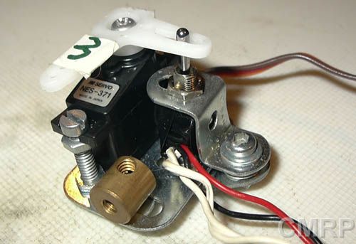
Example of using a small servo to operate a DPDT switch
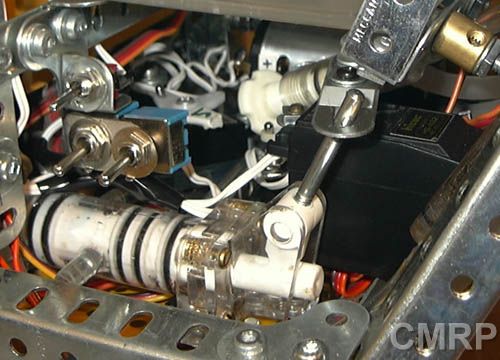
Example
of using a standard servo to operate a mechanical function. Here it is used to
operate a hydraulic valve.
TIPS
HOME