

PROJECT 6
December 2002
MODIFYING M.O MOTOR CASINGS TO ACCEPT MABUCHI MOTORS
Anthony's solution to fitting the Mabuchi motors.
Chris's solution to fitting the Mabuchi motors.
My brother and I came across a lot of old stock of M.O casings while visiting our local dealer one afternoon.
The idea came up of fitting the more powerful "pile" motors which our dealer also had lying around. They are replacement motors for the pile motors, made by Mabuchi, which use rare earth magnets. They run from 6 - 15V. Translation: dynamite in a small package. However, the motors are slightly longer than the French casing, (with a brass bushing in front, and two copper lugs at the back). Obviously too big to fit into an M.O casing.
I must warn you readers, extreme brutality was practiced in this project!
Hacksaws, grinders, files etc.. were used to permanently alter the M.O casings.
Scan of an original M.O kit. At the right you can see the underpowered 6 volt motors supplied.
Anthony describes :
"I noticed that in the lot of casings that I bought, there were an uneven number of halves. This set the mind to work. Either I machine out the front and back of a casing and make it obvious that the casing has been tampered with, or I conceal the motor by some other devious means.
It dawned on me that if I use the useless spare body and chop it into segments, I could extend the length of the three complete cases by 5mm. The photos illustrate the process. I then superglued the casing together.
To complete the motors, I roughened up the 2mm shafts with a file, then degreased them before using Pratley Steel putty to create a 4mm output shafts. Wetting your fingers and pressing the putty on, rather than "rolling" it on, allows the putty to properly bed into the shaft.
The next part is a bit dodgy. With some care, you can sand the shafts down to the correct diameter with a set of files and some sandpaper, with the motor running. Remember that the original Pratley Putty is slightly water soluble, so the final finish can be achieved with relative ease. You may want to keep a vacuum cleaner hose running close by to suck up the loose dust generated by the filing/sanding, preventing it from entering the bearings."
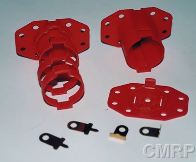
All that’s needed is a spare body casing sliced into 3 equal parts to accommodate a longer motor. Note hole and modified end piece in the lower right of the picture, to allow oiling of rear bearing.
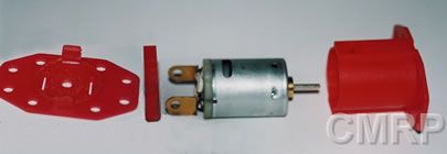
The motor before assembly. Note the modified contacts soldered into place using a short length of wire.
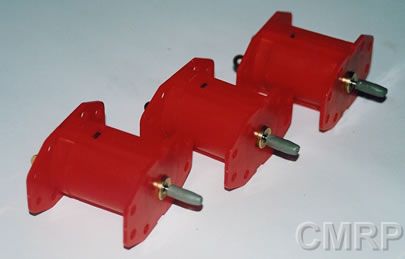
The finished motors, just prior to sanding the shafts to their final diameter. Note that the rectangular holes originally intended for plastic tabs coincidentally line up with inspection holes in the side of the metal motor casing. This allows some degree of cooling. Also note enlarged hole in front casing to accommodate bushing of motor.