DIESEL LOCOMOTIVE
January 2003
DIESEL LOCOMOTIVE MODELPLAN
Bogies and Chassis
Mounting the components and The Track
The Bogies
The
frame is constructed with 4½” and
7½” girders.
Across the top as pivot mount and motor mount are
4½” flat girders.
Below the middle 4½” flat girder is a
4½” angle girder bolted together via their oval
holes. In
the centre an 8-hole bush wheel bolted bush up as per the
pivot. One
hole from the ends, 1½” flat girders are bolted on
the inner edge of the 7½” girder and a trunnion
(Fig 2a) bolted flush to it. ½” bolts are used, with a
collar in between and another trunnion and 1½”
girder on the inside for thickness effect.
The wheels are built up from a wheel flange (p#137) and a face plate (p#109), spaced with plastic collars and ½” bolts so not to distort the wheel flange. The wheels roll on 4½” rods, spaced away from the inner trunnion with washers. 
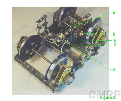
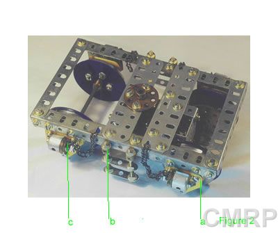
On the outer edge of the trunnions, chimney adaptors are bolted on. 11/8” bolts in the end hole hold a pulley and a piece of chain on as to represent the brake cylinders (Fig 2b). 2” threaded rods carry two 1½” thin strips as steps and are held onto the center of the 7½” angle girder lock nutted to collars (Fig 2c) bolted onto the girder. |
An MO
motor is bolted to the open face of the 1½” square
channel piece (p#160g). The motor shaft carries a worm. The worm meshes
with a ½” pinion carried on a 2” rod in the top
center hole. On the outer end of the shaft another
½” pinion (Fig 3a) meshes with a 57T gear running
on a 2½” rod.
A 15T pinion (Fig 3b) rides face to face with the
57T gear. The
15T gear meshes with a 60T on the 4½” driving
shaft.
½” angle brackets (Fig 3c)
are used to bolt the 1½” square channel piece to
the underside of the 4½” flat girder. The switch
actuator (Fig 3d) is bolted to the underside of the MO,
spaced appropriately to actuate the switch on the
track. The electrical pick up is a hinge (Fig 3e) bolted to the MO as insulation. A 2½” narrow strip is bolted to the other half of the hinge. The screws with washers are to weigh down the pick up for better contact. The positive wire to the MO is bolted to the 2½” narrow strip and the negative to the frame of the bogie. |
The
chassis is started with bolting a 3½” x 5½”
flat plate (Fig 4a) to the middle, oval holes of a
24½” angle girder.
Bolt another 24½” angle girder on the other
side of the plate. On
either end of the 3½” x 5½” plate, bolt on a
3½” x 5½” plate. Next, bolt on 2½” x
5½” plates to the ends of these. Next is a
5½” angle girder by its oval holes with outer edge
facing toward the middle, 3 hole space and another
5½” angle girder by its oval holes with outer edge
facing outside. Next are two 5½” strips next to
each other and finally a 3½” x 5½” plate on
the ends. 2½”
angle girders are butt joined to the 24½” angle |
girder
on both ends, each side.
Bolt a 4½” angle girder (Fig 4b) to the
middle of the 24½” angle girder by its round holes,
on the outside to form a U girder. Butt join
two12½” angle girders (Fig 4c) to the ends of the
4½” angle girder to form a U girder along the
length of the chassis. This will form the mount for the
cover. Using 2½” strips (Fig 4d), bolt then in an X pattern between the 5½” angle girders, front and rear. On top of the X, bolt a double arm crank, boss up. Bolt a 1½” rod in the boss as the mount for the bogies. The rod will pass through the bush wheel on top of the bogie, and be tightened with a collar underneath. Pick one end to be the front, and using two angle brackets, tighten a 5½” strip (Fig 4e) on to close up the U girders. Bolt two cranks (Fig 4f) to the 5½” strip nearest to the foremost 5½” angle girder. This will be the pivot for the driver’s seats. Bolt three 2½” x 1½” flanged plates over the top of the front 5½” angle girders. |
The same cover is done for the rear (optional). On the rear cover, bolt a threaded collar (Fig 5a) to the centre flanged plate. This will form the mount for the head end engine. Using 2” rods, lock nut a 5½” angle girder (Fig 5b) to the end. Spread evenly from the middle of the 5½” angle girder, lock nut another two 2” rods. Tighten collars one hole from the end on the side of the U girder as the outer railing supports. Across the top of the 2” rods, lock nut a 5½” narrow strip and fish plates on the end. Butt join three 5½” strips from the edge of the 5½” angle girder to form the catwalk. |
|