n

DIESEL LOCOMOTIVE

January 2003

DIESEL LOCOMOTIVE MODELPLAN

INTRODUCTION

Bogies and Chassis

Bumpers and Undercarriage

Cabin and Body

Roof and Fans

Optional Components

Mounting the components and The Track

PARTS LIST


Rear Bumper


At the rear bolt a 1½” angle girder to the 3½” x 5½” plate (Fig 6a) by its round holes with the oval holes facing down and rearwards. 

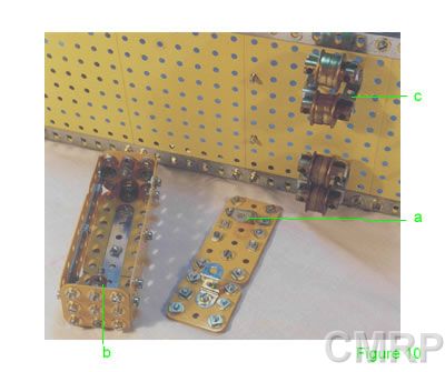
Construct the rear bumper by stacking six 3½” strips on top of each other, next to another six 3½” strips joined at the ends with fish plates and ½” bolts. Lock nut two tension springs to the top bolts to represent electric and hydraulic connectors.  A coupling is bolted to the lower 3½” strips, and angle brackets and obtuse angle brackets form the coupling. 

Using ½” bolts in the top strips, bolt the bumper to the 1½” angle girder. 

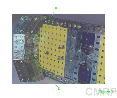
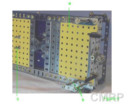
One hole from the rear, lock nut a 2” threaded rod (Fig 6b), and two holes later another 2” rod in the U girder. Lock nut two 1½” narrow strips on to form steps.  Do this on both sides.

Note the two ¾” bolts (Fig 6c). They are bolted to the 2½” x 5½” plate to form stops for the bogies. They stop the bogies from spinning 180 degrees when transporting and only allow limited bogie travel left and right.

CowCatcher


A 2½” flat girder (Fig 7a) is bolted via its round holes to the middle of the 5½” strip across the front of the chassis.

1½” strips (Fig 7b) hold the top three center 2½” strips (Fig 7b) together. On the lower 2½” strip, obtuse angle brackets and fishplates hold the bottom two 2½” strips on.


Obtuse angle brackets on the ends of the center strips hold the end 2½” strips on.  At the end of the outer strips 1½” strips and fishplates hold the strips together.

A coupling is bolted to the second center strip and obtuse angle brackets and angle brackets are bolted together and onto it to form the coupling. Tension springs represent electrical and hydraulic connectors (Fig 8).

Fuel Tanks


Bolt an 8-hole bush wheel to the inside of a wheel flange.  Secure a 4½” rod (Fig 9a) to the bush wheel.

Place 3/8” bolts (Fig 9b) through the holes in the boilers to mount them to the chassis.  Secure a ½” pulley as the fuel filler. The opposite wheel flange is bolted in place on the 4½” rod through the semicircular gap at the end of the boiler.

 Battery Box


Join a 3” x 3½” plate to a 1½” x 1½” plate with a 3½” strip.  Above bolt two reverse angle brackets (Fig 10a) seven holes apart as the mount to the chassis. Screws are put in “nut up” to form the battery studs in the lid. This forms the “lid.”

Join three more 3” x 1½” plates to three more 1½” x 1½” plates as above and form a box using angle brackets and 1½” x 1½” plates as the ends.  Bolt collars (Fig 10b) into the top middle holes of the end plates to allow the lid to be screwed down.


Brake air cylinders

Secure eight ¾” flanged wheels face to face with 1” rods. Use part #825a (thin strip reverse angle brackets) (Fig 10c) secured to the bosses of the ¾” flanged wheels. The reverse angle brackets are then bolted to the underside of the chassis.


Bogies and Chassis
    HOME    Cabin and Body